
Holding Current Reduction type Z KD H 211
The holding current reduction Z KD H is an electronic control gear for solenoids. Depending on the application and the corresponding application, a higher attraction force or a lower energy demand can be reached with the same solenoid size.
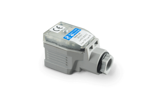
Design: connector housing DIN EN 175301-803
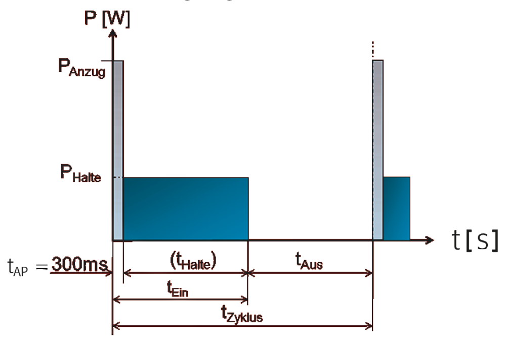
Holding current: adjustable, controlled with pulse width modulation (PWM)
Pulse duration attraction current: 300ms
Input voltage: 9.6 V… 28.8 V DC
Attraction current: 10 A max.
- Holding current: 0.1 A … 3 A max.
- Plug insert and therefore cable outlet can be turned in 90 degrees steps
- Protection class: IP65
- Fastening with central screw M3
- Incl. sealing
Energy and resource efficient control of solenoids via holding current reduction
The solenoid actuator
The solenoid is an actuator which conducts mechanical movements based on the force of the electromagnetical fields.
Principally, it captivates by its simple form of control: by loading with tension, it conducts its movement; basically, neither position switch nor further control elements are needed.
On closer inspection, the physical basis of the actuator principle contains great potentials regarding the optimization of energy and resources which can be achieved by an optimized electrical control.
In order to comprehend the solution approach of the holding current reduction, the relevant physical correlations will be demonstrated here in simplified manner.
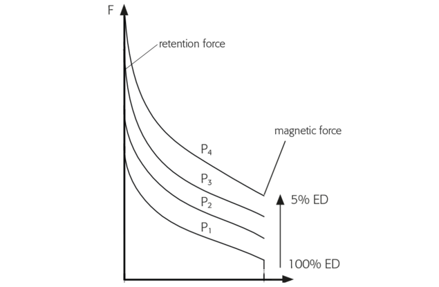
Magnetic force subject to stroke and/or air space and electrical performance
Magnetic force and stroke of the solenoid are the decisive parameters for the selection, they are mutually dependent.
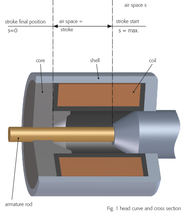
The picture on the right shows the solenoid in profile view, and the curve above shows exemplary progressions of the magnetic force subject to stroke (air space between armature and core) for various electrical performances (P) and/or to switch-on time (ED).
As a conclusion, the magnetic force increases with the electrical performance, however, decreases with enlarging air space, i. e. the distance between armature and core.
Note:
The head curve describes the force progression subject to the air space within the solenoid. So it makes sense to read it from right to left.
stroke start position = right
stroke end position = left
The relation of performance P20, stroke initial power and switch-on time can be seen in the chart, example device G TC A 050.
If performance is increased by approximately 16 times to 270W, power increases by approximately 6 times, the device itself, however, may be operated with only 5% ED
(15 s on, 285 s off).
Due to its manifold characteristics, selecting a solenoid usually is an iterative process. For better comprehension, we confine ourselves to a simplified manner.
If a first choice of the necessary stroke is taken, the necessary power has to be compared with the magnetic forces. In most applications, the crucial point is the stroke initial power (example: G TC A 050 bei s = 10 mm).
In any case, the retention force is higher in most application cases.
| conventional remedy | impact | |
| stroke initial power too small | implementation of a bigger solenoid
|
|
| inrease of electrical performance |
| |
stroke starting power too high | implementation of a smaller solenoid |
|
| decrease of electrical performance |
| |
| utilization of the device with excessive power |
|
In order to optimize the starting power, the solenoid is operated with a higher electrical performance by adapting the winding (number of windings and wire diamenter of coil); this is called "overfluxing". Within a determined 300 ms, the solenoid has reached its final position, the electrical performance is reduced by limiting the current. Now it is possible to adjust the retention force via the holding current's setting possibilities in line with what is demanded of the application.
Depending on the application, the implementation of a holding current reduction allows for downsizing the solenoid by up to 4 sizes.
In many applications, the solenoid's retention force is not fully utilized, on the other hand, heating the device in its final position has even more disadvantages due to the electrical loss.
If the solenoid is controlled by holding current reduction, the retention force as well as the energy consumption and heating can be reduced to necessary levels by adequately setting the holding current.
For the optimal dimensioning of a solenoid control, we recommend taking both control system and solenoid into consideration. For this, we are competent advisers for our customers. In case of need, please see our technical data sheet Z KD H 211.
We kindly ask for your understanding that dimensioning specified for certain applications and producing the device variant that might be needed is only possible for series production quantities.
 +49 8331 1040
 info@magnet-schultz.com