


Electromagnets
Definition
An electromagnet is the general term for all types of electromagnetic actuators.
The most important information in brief
- The electromagnetic principle is particularly suitable for realising small strokes, fast, with great force and little effort in terms of actuation and mechanical integration.
- When a current flows through a coil, electromagnets generate a magnetic field that is guided by iron parts to an air gap, where magnetic poles with attractive force, the so-called magnetic force, are formed.
- The magnetic force is variable by controlling the coil current and is used for linear or rotary movements as well as for holding or braking components, but in particular often as a drive for solenoid valves.
- Important mechanical parameters are magnetic force, lifting force, holding force and lifting work. The force-stroke characteristic can be falling, horizontal or rising.
- Electrical parameters of electromagnets are nominal voltage or limit current, duty cycle, rated current, test current and nominal power.
How do electromagnets work?
In principle, electromagnets are devices that generate a magnetic field by means of a current-carrying coil and guide it through a suitable iron part to an air gap. Magnetic poles form there, between which a magnetic attraction, the magnetic force, prevails. If there is no current at the coil, no electromagnetic force is generated; if the coil current is regulated, the magnetic force is adjustable. Depending on the design of the iron parts, the magnetic force is used to perform linear and rotational movements or to generate holding forces on components, thereby braking or fixing them.
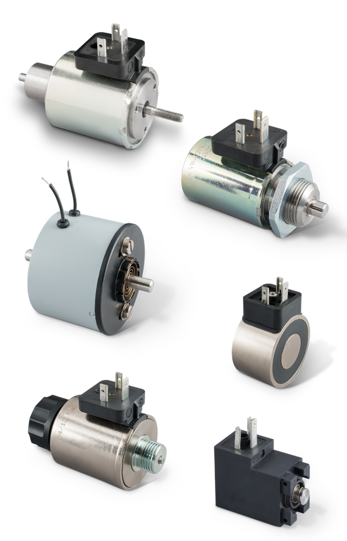
Table of contents
Basics
• Creation of the magnetic field • Use of the magnetic field • Magnetic force as a function of stroke and air gap
Mechanical parameters of linear solenoids
• Magnetic force • Stroke force • Holding force • Magnetic force vs. stroke characteristic • Work • Rated Work
Electrical parameters solenoids
• Rated voltage • Voltage tolerance • Rated current • Test current • Rated Power
Thermal behaviour and operating mode
Types of solenoids
• Differentiation according to voltage type
• Differentiation according to type of construction
• Differentiation according to the type of movement
• Differentiation according to controllability
Explanation of the device types
What is the difference between a pulling or a pushing solenoid?
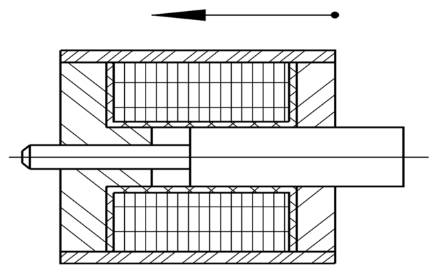
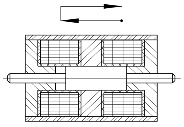
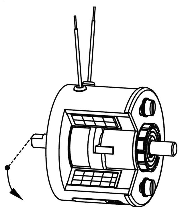
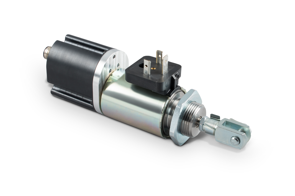
The distinction between pulling and pushing solenoids results from the constructive possibilities of flange-mounting at the moving component, the armature.
The figure shows the basic design of a solenoid, especially a linear solenoid in the unpowered initial position. When energized, the armature and armature rod move in the direction of the arrow.
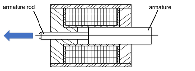
If the solenoid is to be used in pressure mode, it is flange-mounted to the armature rod.
If the armature is hinged - possibly also via a 2nd armature rod not shown here - then the solenoid is inserted as pulling version.
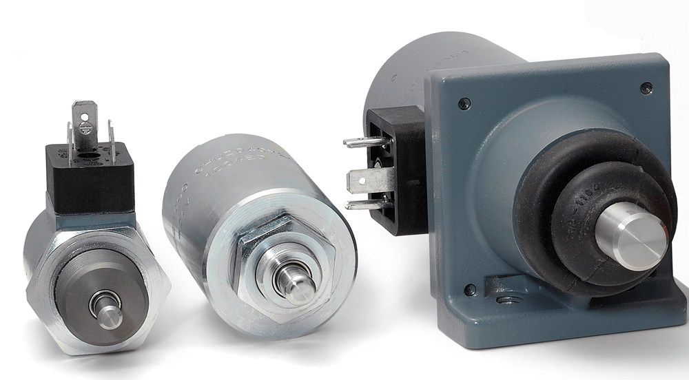
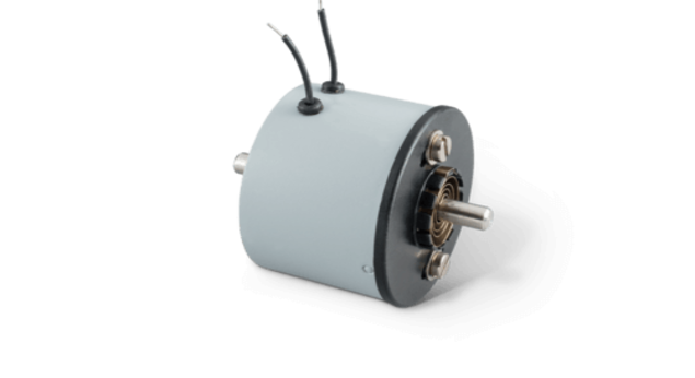
Product examples of pulling solenoids: (G TA F, G MC X, pulling valve solenoid with needle)
Product examples of pushing solenoids: (G AA, G MC X, G SC X)
Depending on the installation, different designs can be used both as pulling and pushing solenoids: (G TC A, G FC X)
How is a DC solenoid connected?
This depends on the available voltage source.
A DC solenoid is directly connected to a DC power source. The voltage must correspond to the nominal voltage of the device.
If AC voltage is available as the voltage source, the electrical connection can be made via a rectifier.
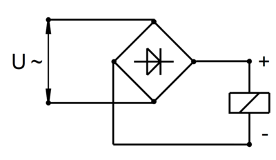
If the supply voltage is 230 V, the DC magnet must be designed for 205 V when silicon rectifiers are used.
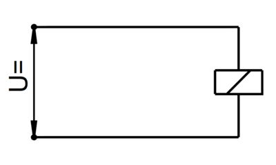
The solenoid generates an overvoltage when it is switched off, how can this be limited?
The inductance associated with a DC solenoid causes high switch-off overvoltages, which can cause the electrical insulation to break through or damage other electrical components in the circuit.
The most common method of limiting the cut-off overvoltage is a diode-protective circuit.
For further information, please refer to our Technical Explanation GXX.
Which parameters does the force of a solenoid depend on?
The force of a solenoid is directly related to the current flowing through the coil. If a higher current flows, the force of the solenoid increases.
In addition, the size of the air gap or the position of the armature has a considerable influence.
The solenoid heats up during continuous operation. Is this a malfunction?
The self-heating of an energized solenoid is physically conditioned and basically no malfunction. If current flows through the coil of the device, the electrical energy is converted into thermal energy due to the ohmic resistance of the coil. This causes the solenoid to heat up. Depending on the design and ambient conditions, this results in considerable surface temperatures. If a device is operated under incorrect conditions, the temperature can rise above the permissible temperature, which can lead to a damage of the device. The maximum permissible temperature (limit temperature) is between 90°C and 250°C; it is determined by the choice of insulation materials.
Please refer to our Technical Explanation GXX for further information.
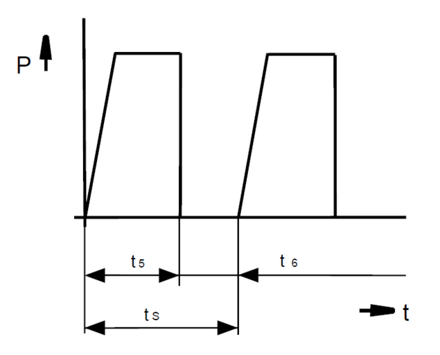
What does the term "duty cycle" mean?
The duty cycle t5 is the time in which the supply voltage is applied to the solenoid.
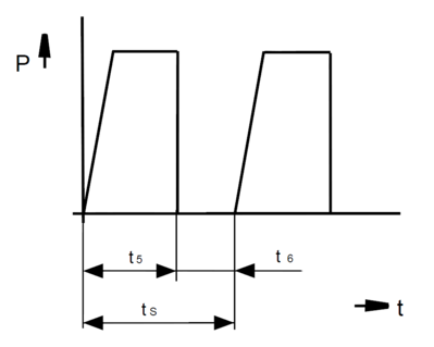
t5 = duty cycle (s)
t6 = de-energized period (s)
tS = cycle time (s)
P = power (W)
t = time (s)
The relative duty cycle ED in % is the percentage ratio of duty cycle t5 to cycle time tS.
%ED = duty cycle / cycle time * 100
In which way is it possible to reduce the self-heating of a solenoid?
The heating of a solenoid can be influenced from two directions:
- Reduction of the supplied energy
or
- Improvement of heat dissipation through cooling
The use of a holding current reduction Z KD H 211 is recommended to reduce the supplied energy.
In your data sheets, different magnetic forces are specified for different operating modes or duty cycles. What does this refer to?
With regard to solenoids, it is possible to increase the magnetic force at the expense of the permissible duty cycle by installing coils with different powers. For this reason, the magnetic force specifications for
Continuous operation (operating mode S1 / relative duty cycle 100%)
as well as
Intermittent operation (operating mode S3 / relative duty cycles 40% / 25% / 15% / 5% )
are indicated.
In the following, an excerpt from an exemplary data sheet for linear solenoids can be seen:
If you take a look at the magnetic force values for the different strokes in each column, you can see how the magnetic force increases with decreasing duty cycle.
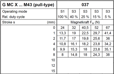
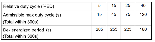
The relative duty cycle for solenoids refers to 5 minutes (=300s).
In the concrete example, it refers to the duty cycles listed in the table:
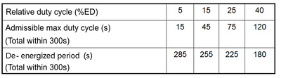
In the case of several switch-on processes within 300s, the switch-on times and breaks without current are added.
The force of the solenoid used is too low. How do I proceed?
In the first step, we recommend checking to which extent the required force can be reduced by optimizing the overall application.
With regard to solenoids, it should be observed that the magnetic force generally decreases with increasing air gap / stroke. If the stroke and possible idle strokes can be reduced, it results in the solenoid being operated in the range of the higher magnetic force.
Principally, solenoids can be used to increase performance by reducing the duty cycle. For this purpose, the device is designed with an adapted factory-made coil winding.
Your responsible Technical office will be happy to assist in solving your problem.
Which voltage is used to operate a solenoid?
As a rule, a solenoid is operated at its rated voltage as indicated on the rating plate together with the operating mode or relative duty cycle.
The nominal voltage must be specified when a solenoid is ordered. The standard voltage and the maximum possible nominal voltage are specified in the respective data sheets.
Regarding proportional solenoids, the permissible limit current IG is relevant instead of the nominal voltage.
I would like to operate my solenoid with a voltage other than the nominal voltage. Is this possible?
As a general rule, solenoids have to be operated exclusively at rated voltage.
If a solenoid is not operated at its rated voltage, the technical data given do not apply. If the voltage is below the nominal voltage, the force values are not reached and the solenoid is not fully used. If the operating voltage is above the nominal voltage, the device delivers greater forces, but the coil is overloaded, the magnet overheats, and there is a danger that the device will be destroyed and may start to burn.
Taking into account a reduced duty cycle, a solenoid can be overexcited using a suitable control (holding current reduction). More information can be found in the data sheet Z KD H.
Does the direction of movement of a solenoid change when the polarity at the connectors is changed?
No.
If the polarity is changed the direction of the electromagnetic flow in the solenoid changes; however, the direction of movement of the armature remains the same because the direction of the force effect in the air gap does not change.
This is not the case when a permanent magnet is installed in the magnetic circuit. In this case, we speak of a polarized magnet system. In the case of polarized solenoids, care must therefore be taken to ensure that the polarity of the connection is correct.
Which electrical power does the electromagnet need?
The required electrical power (W) is specified in the technical data sheet depending on the relative duty cycle. The corresponding current must be calculated from the nominal voltage and the nominal power.
What are the differences between proportional and ON/OFF solenoids?
As for looks, there are no differences between proportional and ON/OFF solenoids. The differences can be found in the shape of the characteristic curve, in the precision of the bearing and magnetic circuit as well as in the electrical control. While a proportional solenoid can be used to set up a position control system that allows the stroke points to be approached repeatedly and with repeat accuracy, an ON/OFF solenoid is designed to reach the end positions without intermediate positions.
Why is it not possible to implement position control with a standard linear solenoid?
Linear solenoids of our standard program are usually ON/OFF solenoids with an increasing characteristic. This characteristic is not suitable for position control.
An ON/OFF solenoid is designed for its nominal voltage. The current flowing through the coil depends on the resistance of the coil, which in turn changes with the temperature of the coil. Therefore, the required repeat accuracy for position control is not guaranteed.
Basics Solenoids
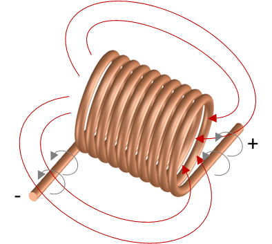
If the coil is energized, an electrical current flows in dependence of voltage level and electrical resistance.
This current creates a magnetic field in the coil, which is demonstrated by the red field lines in the picture.
The coil is usually made of enamelled copper wire since copper has a very good electrical conductivity. For extremely large coils, aluminium is also used as conductor material in special cases in order to reduce weight or cost.
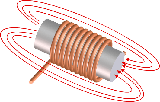
The expansion of the magnetic field considerably depends on the material and its shape through which the magnetic field flows.
Air has a comparatively high resistance against the magnetic field, whereas iron materials such as steel have a high magnetic conductivity and conduct the magnetic field very well.
For this reason, the magnetic field of the coil is guided in steel components. In simplified terms, it can be stated that the magnetic field is amplified by steel components. However, it is correct that there is no amplification, in fact, the magnetic field is weakened only slightly due to the outstanding magnetic conductivity of ferrous materials.
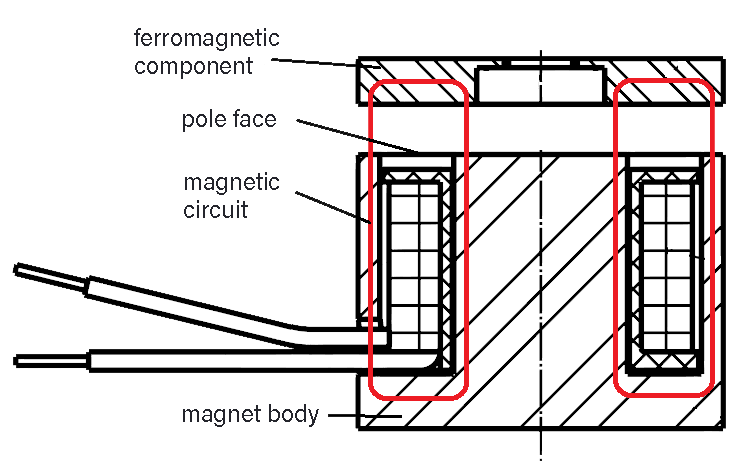
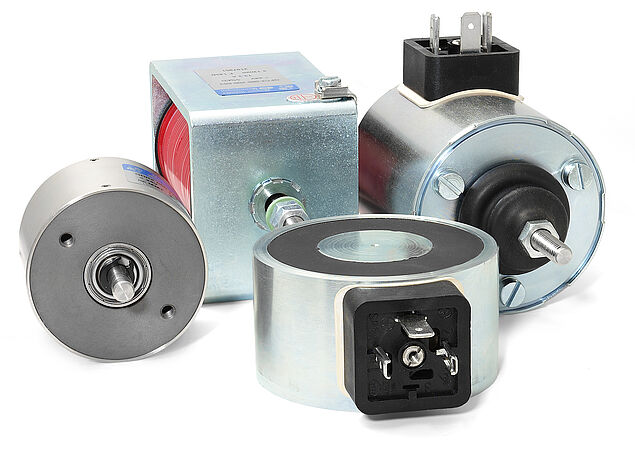
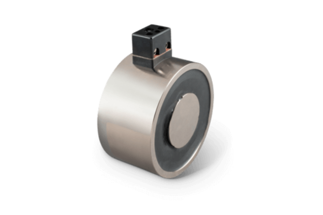
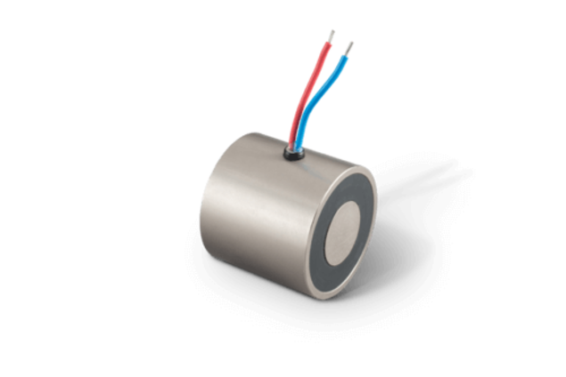
The most ordinary form of an electromagnet is the holding magnet, also called pot magnet. The magnetic circuit consists of a pot-shaped magnet body with internal pole surrounding the coil on 3 sides. The force that can be applied to a magnetic component with this device decreases very rapidly the larger the distance of the component from the so-called pole surface gets.
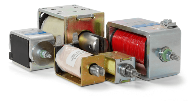
As a rule, if the electromagnet has to function as a linear actuator or linear solenoid, highest possible forces are required with largest possible strokes.
For this purpose, a movable iron part, the armature, is arranged inside the coil at a distance (air gap) from the fixed core.
If the coil is fed with current, the armature moves towards the core and executes the stroke with the dimension of the air gap. The armature's movement can, for example, be led outside the electromagnet via an armature rod through a hole inside the core.
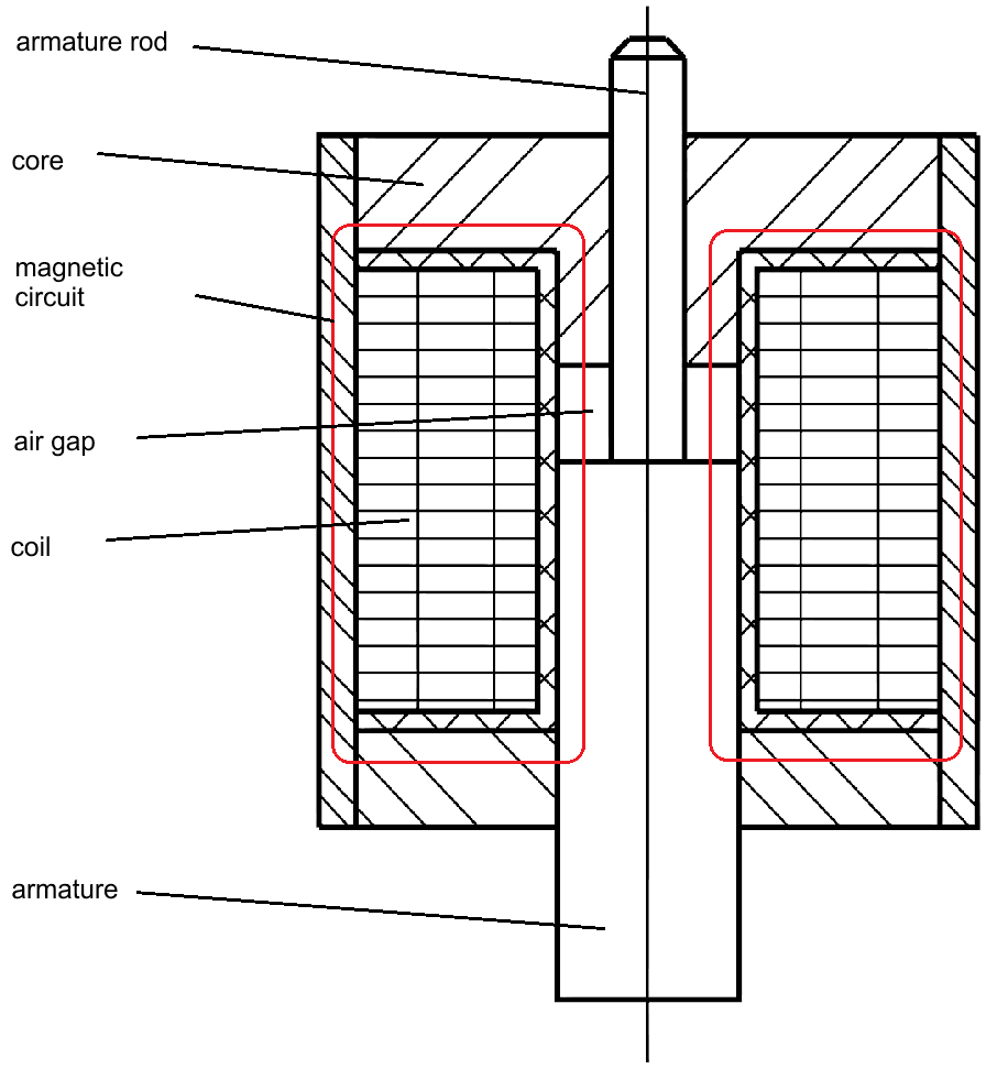
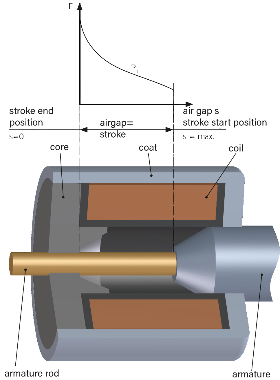
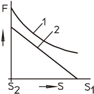
Inside electromagnets, magnetic force and stroke are decisive variables for their selection and they are mutually dependent.
The picture on the left shows a sectional view of a solenoid and the picture above shows the force curve over the stroke or air gap.
The shape of the characteristic curve is determined by the design of the core and armature and can be very accurately determined by using modern calculation tools (finite element method). Fine-tuning is still carried out by adjusting the sample devices' geometries.
Mechanical characteristics linear solenoids
As an example for other forms of electromagnets, the important mechanical parameters for linear solenoids are explained here in simplified manner. Please download detailed information in our Technical Explanation.
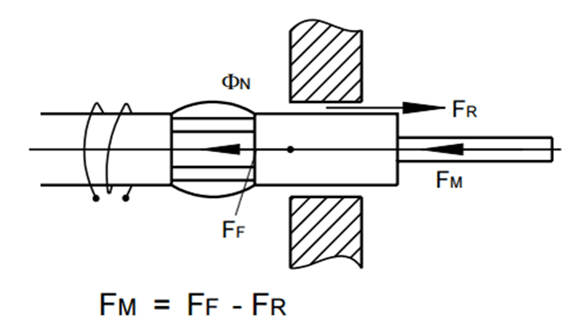
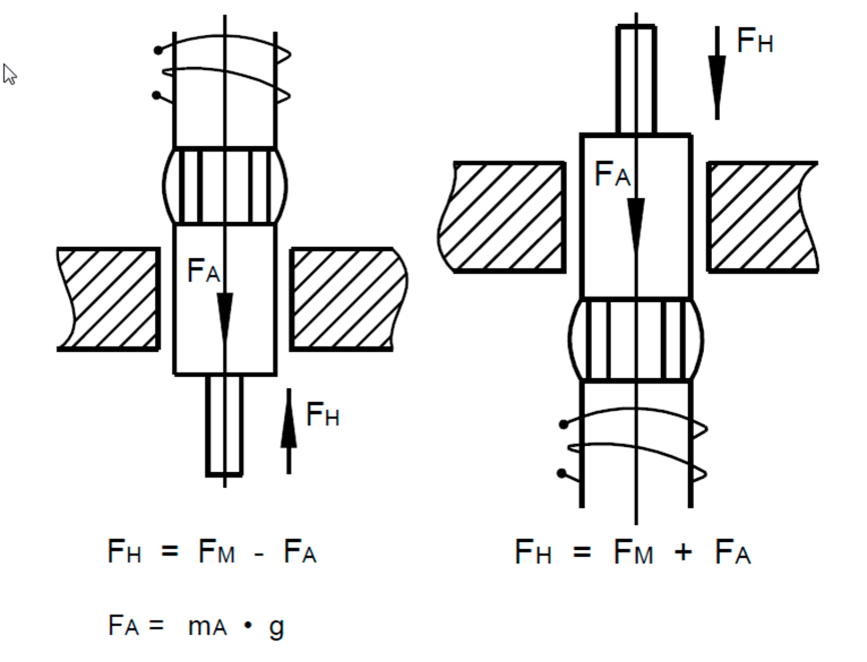
The magnetic force FM is the exploitable part, i.e. the part of the mechanical force generated inside the linear solenoid, with stroke direction in a horizontal armature position which is reduced by the friction.
ΦN = Useful flux (Wb)
FR = Friction force (N)
FM = Magnetic force (N)
FF = Force applied to the armature by the magnetic field (N)
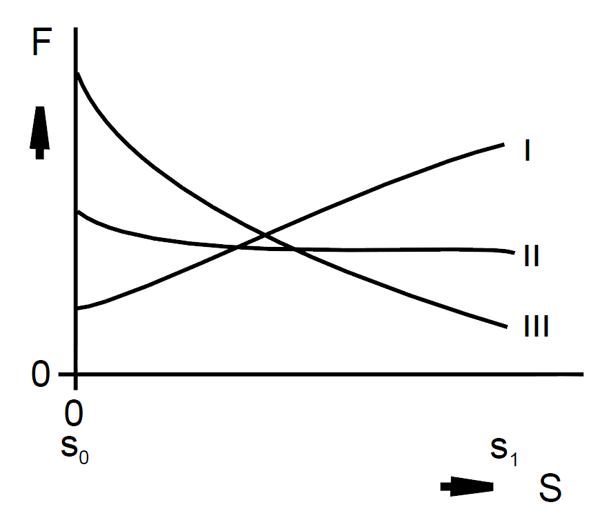
Due to the geometric design of the armature and core, three fundamentally different types of characteristic curves can be achieved.
I. decreasing characteristic curve
II. horizontal characteristic curve
III. increasing characteristic curve
The most common curves are the increasing characteristic curve, particularly suitable for spring counterforces, and the horizontal characteristic curve, particularly suitable for constant counterforces.
The decreasing characteristic curve is rarely used for linear solenoids, it is applied where high friction forces need counterforces.
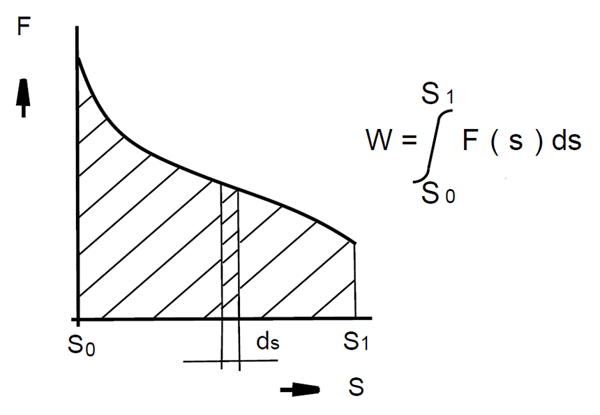
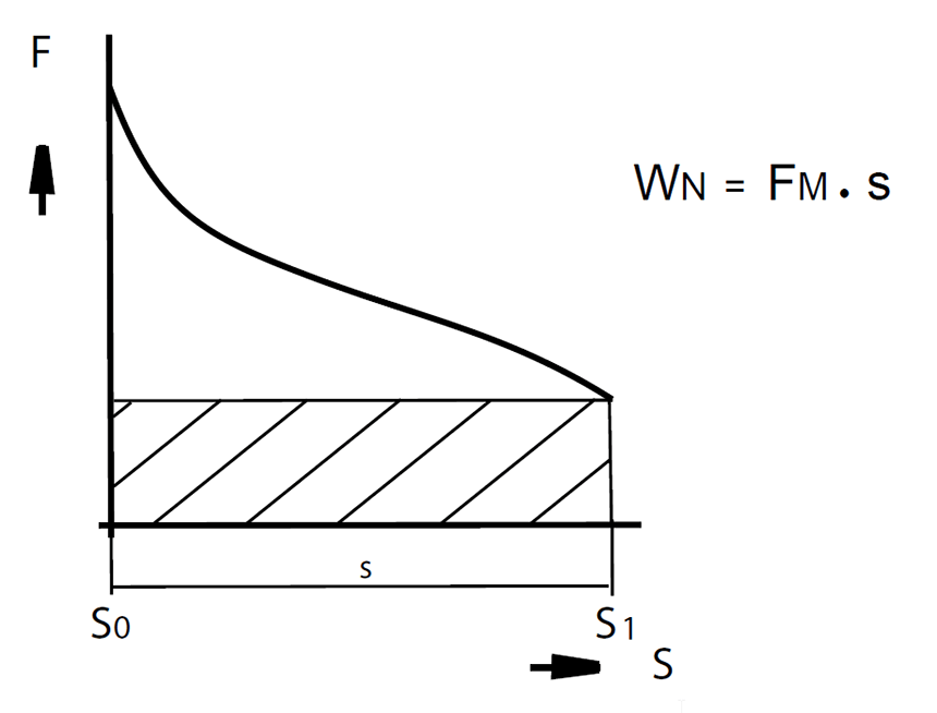
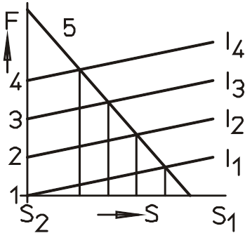
The Rated work WN specified in the data sheets is calculated as the product of the magnetic force FM in the initial stroke position s1 and the magnetic stroke s.
If a solenoid needs to be selected for a new application on the basis of existing specifications regarding stroke and magnetic force, the calculated nominal stroke energy can be compared with the values in data sheets in order to determine an adequate solenoid size, depending on the operating mode. If necessary, please contact your local Technical office.
Electrical characteristics Solenoids
Important electrical parameters for DC solenoids are explained below. Unless otherwise stated, voltage and current specifications are arithmetic average values for direct currents.
For the rated voltage UN, a voltage device is designed and marked. Unless otherwise stated, the values of the data sheets are based on a rated voltage of 24 V. Regarding other nominal voltages, deviations from the specified magnetic forces may occur, due to the different insulation components in the exciter windings, upwards (usually at > 24 V) as well as downwards (usually at < 24 V) .
The Test current IPR is the current which the magnetic force values specified in the data sheets refer to.
It is calculated as follows:
IPr = 0,9 UN / RW
RW stands for the operating temperature resistance of the exciter winding.
The factor 0.9 considers the smallest permissible supply voltage due to the permissible voltage tolerance.
Thermal behaviour and operating mode
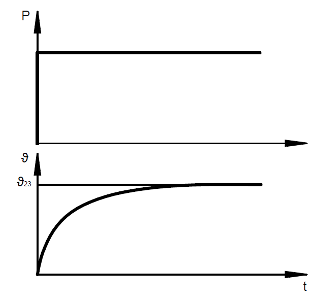
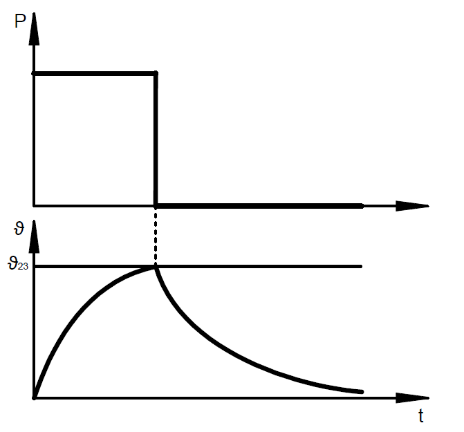
The electrical resistance of the solenoid coil means that an electromagnet heats up as soon as it is energized. The maximum temperature (steady-state temperature) in the coil is reached when the heat supplied by electrical energy corresponds to the amount of heat dissipated by heat radiation; a heat conduction and a thermal equilibrium are achieved.
If a higher electrical power is supplied, the magnetic force increases and a higher winding temperature (steady-state temperature) is reached.
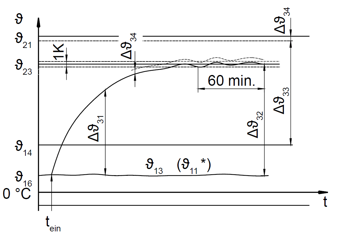
During designing the windings of electromagnets at MSM, care is taken in order to ensure that the temperature of the winding is below the permissible maximum temperature for the insulating materials, taking into account the ambient conditions and the operating mode.
ϑ13 ambient temperature at the end of the measurement
ϑ11 reference temperature (consideration of temperature, influences of media)
ϑ14 upper ambient temperature
ϑ16 initial temperature at the beginning of the measurement
ϑ21 upper limit temperature
ϑ23 steady-state temperature
Δϑ31 excessive temperature
Δϑ32 steady-state excessive temperature
Δϑ33 temperature rise limit
Δϑ34 hot spot difference
tein turn-on instant
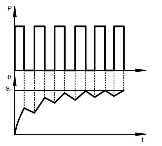
During intermittent operation (S3), switch-on time and currentless breaks alternate in regular or irregular intervals; here, the breaks are so short that the device does not cool down to its reference temperature or output temperature.
The permissible duty cycle is in % and is calculated as follows:
%ED = duty cycle / cycle time * 100
t5 = duty cycle
t6 = de- energized period
tS = cycle time
The force, power and time values indicated on the electromagnet data sheets refer to a cycle time of 5 minutes (300 sec.). For this cycle time, the following permissible maximum values for the duty cycle are indicated in the table on the left-hand side.
Types of solenoids
Solenoids are distinguished and classified according to various criteria. In the following, each criteria is described individually, in practice, combinations can be seen.

Depending on the type of movement of a solenoid, the following term is used:
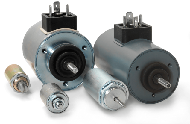
- Single acting solenoids: they perform linear movements.

- Shotbolt locking units as a special form of single acting solenoids, the armature rod is particularly stable, therefore transverse forces can be absorbed.
- Rotary solenoids for rotary movements over a limited angle (max. 110°)
- Holding magnets: they generate a magnetic field which applies attraction forces to a ferromagnetic counterpart.
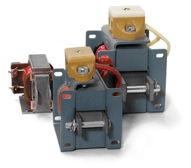
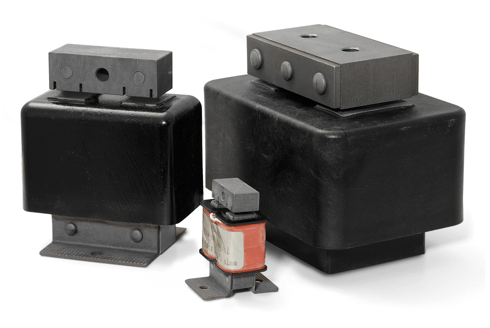
- AC Vibrators for generating small stroke movements that can cause spring-mass systems to vibrate.
Proportional solenoids are equipped with a horizontal or slightly falling characteristic by suitable design measures.
In contrast to ON/OFF solenoids, the proportional solenoids are controlled via current control instead of nominal voltage.
In order to limit the thermal load, the maximum permissible current is specified as the so-called limit current IG. The current control eliminates the influence of the temperature-dependent resistance change of the coil winding.
The magnetic force can now be adjusted by changing the current flowing through the coil. If the solenoid works against a force, a stroke point will be set, depending on the counterforce's extent
Applications which call for special positioning accuracy are equipped with position sensors, making it possible for a control loop to be set up with which reaching and holding certain positions can be controlled precisely.
Explanation of the device types
Depending on the type of motion cycle, a distinction is made between single, double and reverse acting solenoids.
Single acting solenoids are electromagnets in which the movement from the initial position to the end position is effected by electromagnetic force. An external force is required in order to return the solenoid to its initial position, e.g. spring force, weight force, etc.
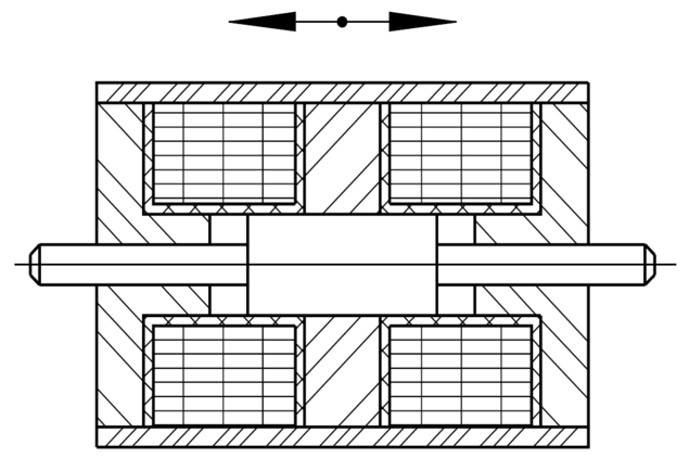
Double acting solenoids (with position zero) are electromagnets in which the movement after excitation of the relevant coil takes place from position zero in one of the two opposite directions. Returning to position zero is achieved by external restoring forces after switch-off. Position zero is the initial position for both directions.
Reverse solenoids (without position zero) are electromagnets in which the movement takes place after excitation of the relevant coil from one end position to the other or vice versa.

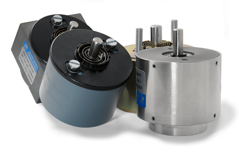
Solenoids that perform a rotary motion are called rotary solenoids.
The single-acting version is the most common of them.
If a return movement is required, a return spring is adapted via suitable spring cage.
As a basic rule and analogically to linear solenoids, a reversible rotary solenoid version with 2 rotary solenoids working against each other can be put into practice.
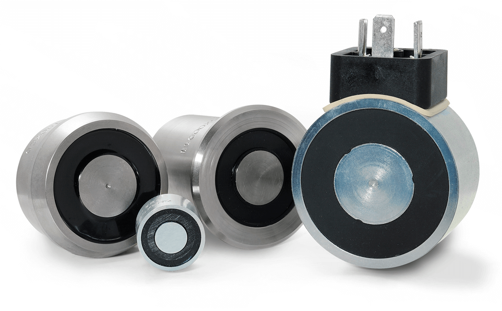
Retaining magnets are electromagnets that generally have no or only very small strokes.
Depending on the type of function, the counterpart is attracted by a magnetic field in energized or de-energized state.
Holding magnets create a magnetic field throughout a power supply connection.
Permanet holding magnets constantly attract magnetic counterparts. The magnetic field is generated by an integrated permanent magnet. If the devices are connected to the power supply, this magnetic field is largely neutralized by the magnetic field of the coil additionally installed.
Advantages of solenoids
Electromagnetic systems are basically in competition with a large number of other types of actuators, for example:
- Electromotive drives with spindle, gear or crank loop
- Electromechanical cylinders
- Pneumatic actuators consisting of cylinder and valve
- Piezo actuators
- Voice Coil Actuators
- Magnetostrictive actuators or translators
- Actuators with shape memory metals
- Actuators with thermobimetals
The electromagnetic actuator has the following qualitative advantages:
- Fast motion with high dynamics
- High forces
- Low technical effort compared to an electromotive solution:
- Simple electrical control
- No mechanical interface (gearbox, etc.) required
- Fixed stroke
- Wide working temperature range
- Low number of moving parts
- Low susceptibility to interference
- High degree of protection and explosion protection according to ATEX/IECEx possible
- Long service life
- Maintenance free
- Large variety of types
- Standard devices available from stock
Frequently asked questions about solenoids
What is the difference between a pulling or a pushing solenoid?
How is a DC solenoid connected?
The solenoid generates an overvoltage when it is switched off, how can this be limited?
On which parameters does the force of a solenoid depend?
The solenoid heats up during continuous operation. Is this a malfunction?
What does the term duty cycle mean?
In which way is it possible to reduce the self-heating of a solenoid?
The force of the solenoid used is too low. How do I proceed?
Which voltage is used to operate a solenoid?
I would like to operate my solenoid with a voltage other than the nominal voltage. Is this possible?
Which electrical power does the electromagnet need?
What are the differences between proportional and ON/OFF solenoids?
Why can I not implement position control with a standard linear solenoid?
 +49 8331 1040
 info@magnet-schultz.com